
Hello and welcome back to another Blightmare dev blog! This post is a continuation of our 2D lighting series which started with the basics here. Last time we saw what a little bit of lighting could do to help our test scene pop a little bit, and today we're going to make it even better by adding some shadows. After all, it just doesn't look right to have the platforms and terrain being lit without casting shadows below. First we will cover a method to add a simple shadow and then we will see what that looks like integrated into the test scene.
To start, we need to precisely define what a shadow is. For the purpose of simplicity while we work on the theory parts, we will consider a box as the test shape that we want to be shadowed:

Adding a light to the mix allows us to draw out where we expect a shadow to be. By carefully analyzing the process taken to create this shadow region, we can start to think about a method that can be implemented in our code.
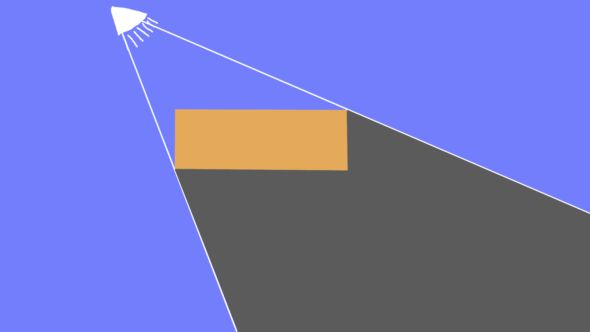
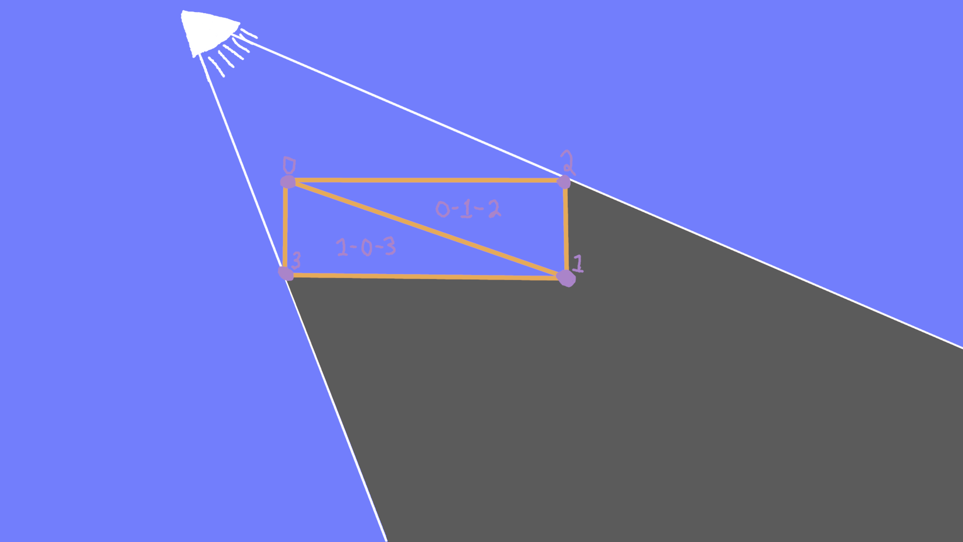
The key observation is that the shadow area is formed by extending out the corners of our box in a direction that points away from the light. The tricky part is to make use of this observation in a general way that creates a region we can make use of. What we need is a way to generate a shape that forms the shadow region. To start thinking about how we can do that, we need to start with how the shape of this box is actually represented. Internally, our box is 2 triangles formed between the 4 corners:
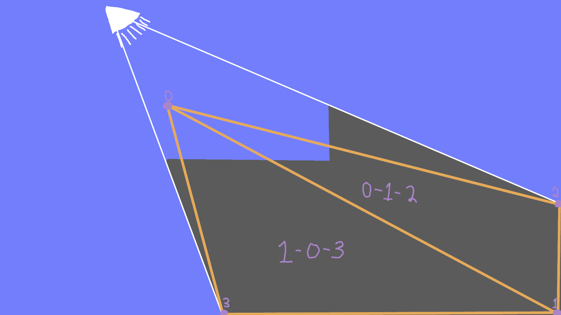
Based on this representation, we can already start to see what we're going to need to do. If we could somehow move vertices 1, 2, and 3 away from the light to the edge of our view, we would really be getting somewhere. Unfortunately, that's not quite going to cover the shape that we want:
It turns out that there's no way to create the shape that we want with only the geometry from our original box. This means we're going to have to generate special geometry for our shadow. If we build the geometry by hand, we can achieve the result we want by adding 2 additional vertices, and 2 additional triangles:
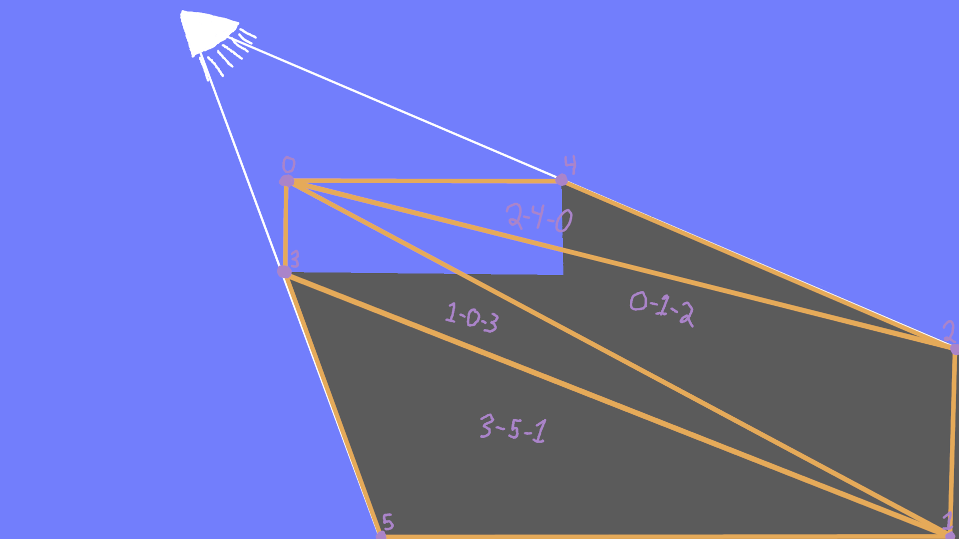
Note that in this version, the numbering has been selected to allow reuse of the original triangles. This is starting to look like it will do what we want! The question now is: how can we build an algorithm that will do this for all positions of the light, and more complex geometry?
In order to answer this question, we need to make a few more observations. If we think about the original edges of our box, we can see that the shadow geometry is formed by altering the edges that are not facing the light. The term "normal" is used to refer to a direction that is perpendicular to an edge. Computing the normal of an edge in 2D is a simple operation given the end points of the edge [x1, y1] and [x2, y2]: [-(y2 - y1), (x2 - x1)]. We can also compute the direction from the light to one of our vertices by subtracting positions. The last thing we need to do is determine if the edge is facing the light (illuminated) or not (shadowed). To do this, we use the dot product between the light direction, and our edge normal. The dot product is positive when these two directions have any common direction, the dot product is 0 when the directions are perpendicular to each other, and it's negative when the directions point at each other to any degree. Another way to describe the dot product is that it computes a value that is proportional to the angle between the vectors being inspected. More specifically, we get the cosine of the angle between the vectors multiplied by the length of both vectors. The cosine of an angle is positive between 90 and -90 degrees, which is exactly the range that we would consider 2 vectors to be pointing in a similar direction. For our purpose, we're only interested in the sign of this value because we don't care how similar they are, just if they are similar at all.
Now that we know how to set ourselves up to move the correct vertex, we need to make sure our geometry is setup to be able to handle all the different light positions that we might encounter. In order to do this, all we need to do is create an extra triangle along each edge. By specifying opposite normals for one of the vertices in our new triangle when compared to the adjacent triangle in the original shape, we will be sure that the resulting shadow geometry will be correct. This is all a bit much to think about theoretically, so here is a picture of our case worked out:
The small red arrows next to the numbered vertices shows the direction of their normal. As you can see, we went from 4 to 8 vertices, but only 4 of the vertices were moved from their original locations. The interesting case to look at is vertices 1 and 6. Here we have 2 vertices in the same position but with different normals. Both of the normals point towards the light however, so they will both be relocated to the edge of the shadow geometry. This is a good example of why we only care about the sign of the dot product.
To bring this all back to Unity, I built the worked example here into a test scene, and we can see it run through the frame debugger:
First the shadow mesh is rendered

Next the lighting is drawn, taking into account the shadowed area
Lastly, the box is drawn on top to complete the image
Putting this altogether then into our original test scene, we can add some shadows onto the platforms, and use the shadow generation method described a few weeks ago for our terrain, and end up with an even better looking test scene:
That's it for today! We've still got quite a ways to go before things look the way we want, but it's certainly an improvement from the start. All of these techniques are used in Blightmare, so if you want to see it in action in the final game, please head over to our Steam page to add Blightmare to your wishlist and pop over to our Twitter to follow further blog updates. Thanks for reading!